Final Integration Project Documentation
Basic Idea
For my final project, I used P5 and Tone.js to integrate graphics and sound to the safe-cracker game that I developed as part of the last assignment in the physical computing module. The object of the game is to rotate a dial, like you would see on a combination padlock or a safe, until you find each number of the combination, indicated graphically.
The game’s interface starts at the physical computing level. Player interaction is controlled mainly from Arduino components. The dial’s movement is controlled with a joystick component, which will be translated to the graphical portion of the game. The physical layer will also include digital output for a user to track their performance in the game.
For the digital component, I have created an interface in P5 that represents the dial on a combination lock. As the user moves the physical joystick, P5 reads this input through Serial Communication and turns the graphical dial accordingly. Once the dial reaches the number needed, the user is signaled. This graphical component also contains the game state, variables, and algorithm. The Arduino component is used primarily as I/O.
For sound, I used Tone.js to bring the game’s sound environment to life. I added sounds to simulate the clicking sounds of opening a lock, the sound when you are close to the number in the combination, and the sound to indicate if you have beaten the high score. These three major components create an immersive experience that feels like you are really cracking a safe.
Media
The video above is a demonstration of all the parts working together. The app makes a noise to guide the user to the code by buzzing in a higher frequency as the user approaches it.
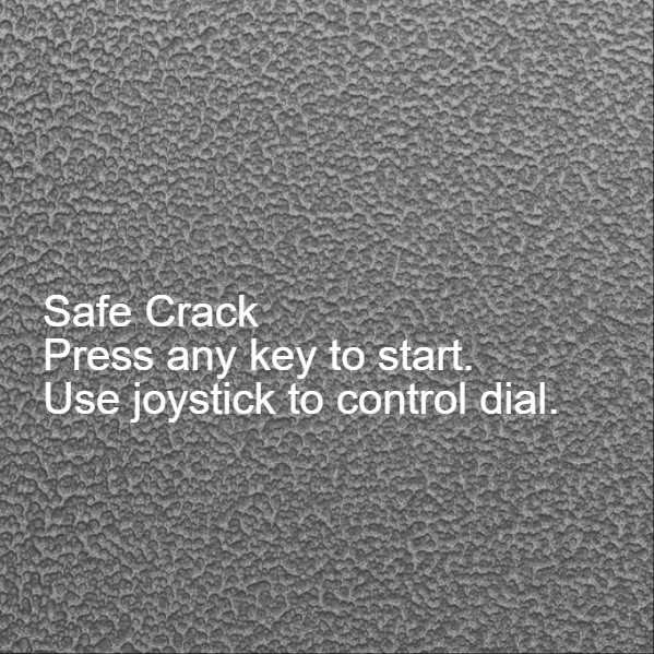
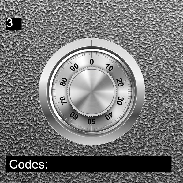
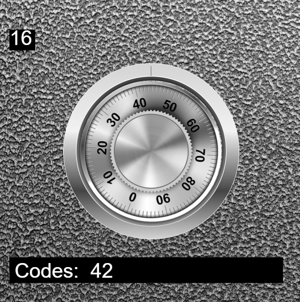
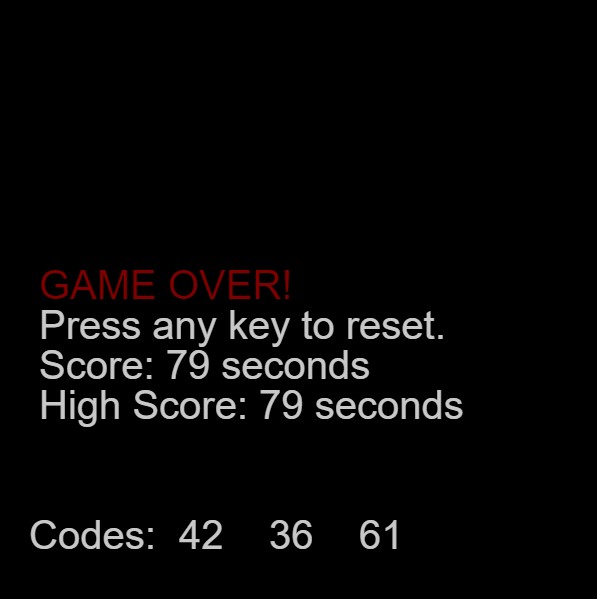
These four images capture the basic stages of the game. The first is the starting screen where the user makes sure that their joystick is connected before pressing a button to start. Then, the dial is turned right until a code is reached. This process is continued in alternating order until all three codes are found.
Diagrams
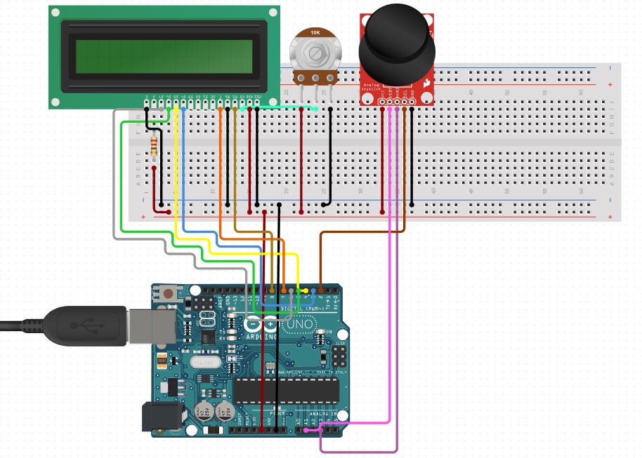
This wiring diagram shows how the arduino is wired. The two main components are the LCD board for displaying codes and the joystick for controlling the dial. It is possible to wire the LCD without the potentiometer, but it is included in this diagram.
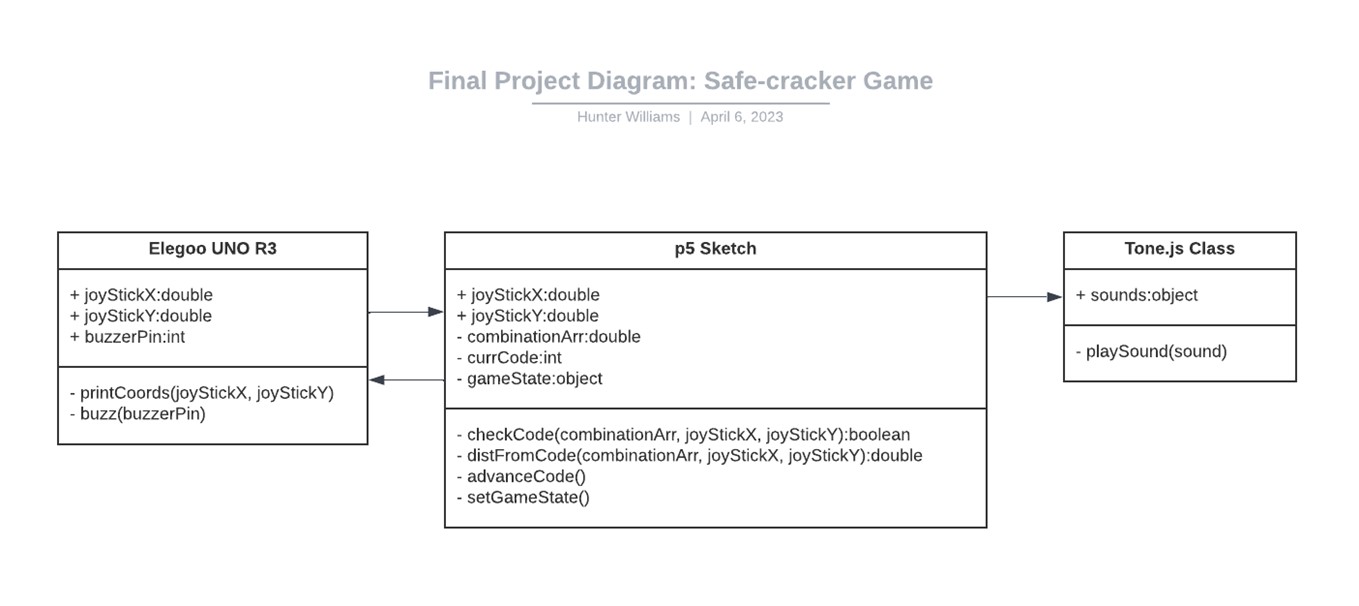
This UML diagram shows the basic structure of the programming elements and how they work together. The arduino communicates with P5 to send the X value to the sketch, the sketch takes the value and adds a fraction of it to the angle at which the picture of the dial is rotated. This angle is where the current code is derived so that the program can compare it to the next randomly generated code.
Future
This game is fairly fun but can become boring after some time. It is not intended to stand alone, but would work well as a minigame. In future development, the following features would be quite handy.
- Better sounds. More realistic and useful sounds would create a better experience for the user
- More inputs. Mouse or keyboard input would help users without arduino kits.
- Better RNG. Random numbers as of now are "truly" random, and sometimes collide with each other
- More intelligent color choice and interface design.